Antweight Battle Bot
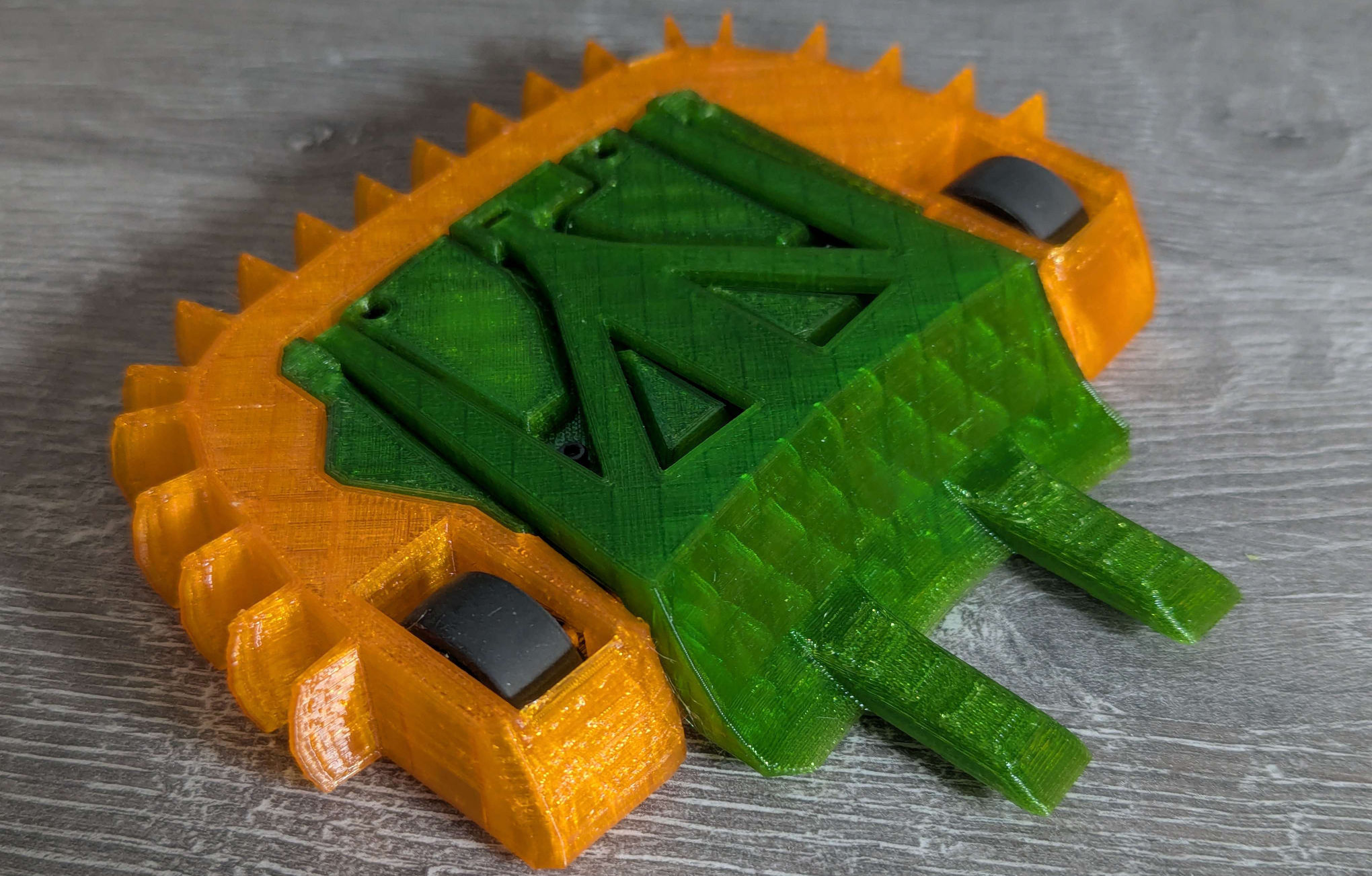
EF1 (Experimental Flipper One) is my first battle bot, built to compete in the UK Antweight class at under 150g using 3D-printed parts.
EF1 (Experimental Flipper One) is my first battle bot, built to compete in the UK Antweight class at under 150g using 3D-printed parts.
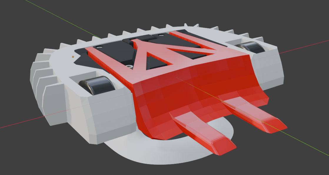
EF1 was designed using Blender. Conventional wisdom suggests using parametric CAD software, but I have more familiarity with Blender and I knew it would get the job done. I started by downloading the CAD models for the components I would be using and then experimented with different component layouts. I modelled most of the chassis by hand, but used Blender's Boolean modifier to create snug clamping fitments around components like the motors.
I wanted to minimise the use of handmade parts, as they are time consuming to make and can be quickly destroyed in an arena. 3D printing was the natural choice: it offers design flexibility, and when parts break, I can simply print replacements.
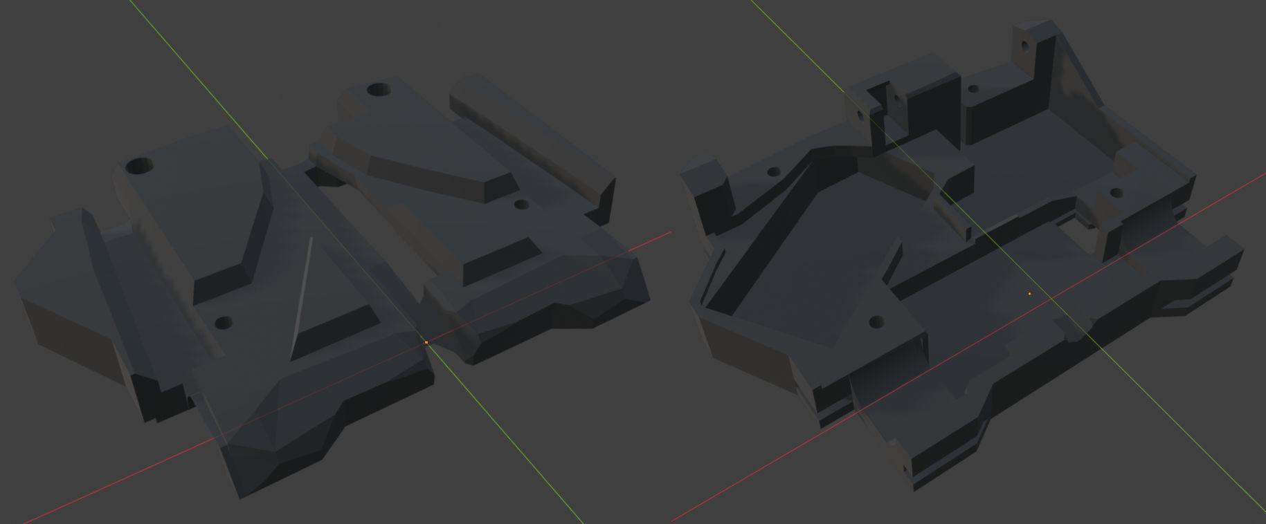
The chassis is made out of 3D printed PCTG (Polycyclohexylenedimethylene Terephthalate Glycol-modified). It was chosen for its PETG-like properties with stronger layer adhesion and better impact absorption. It is also cost effective and easy to print. A 95A hardness TPU was considered for the chassis, but as this is my first bot I decided to keep things simple with a chassis that doesn't flex.
The chassis was designed to be as compact as possible, with the space between components filled in for added strength. Fitting the wiring into this robot was challenging as I didn't fully appreciate how much space wires take up. All cables had to be cut as short as possible to remove slack, and I had to revise the design to accommodate the connectors.
EF1 uses a straightforward electrical setup: a Malenki Nano ESC/receiver combo board, two N10 600 RPM gearmotors for drive, and a servo to actuate the flipper.
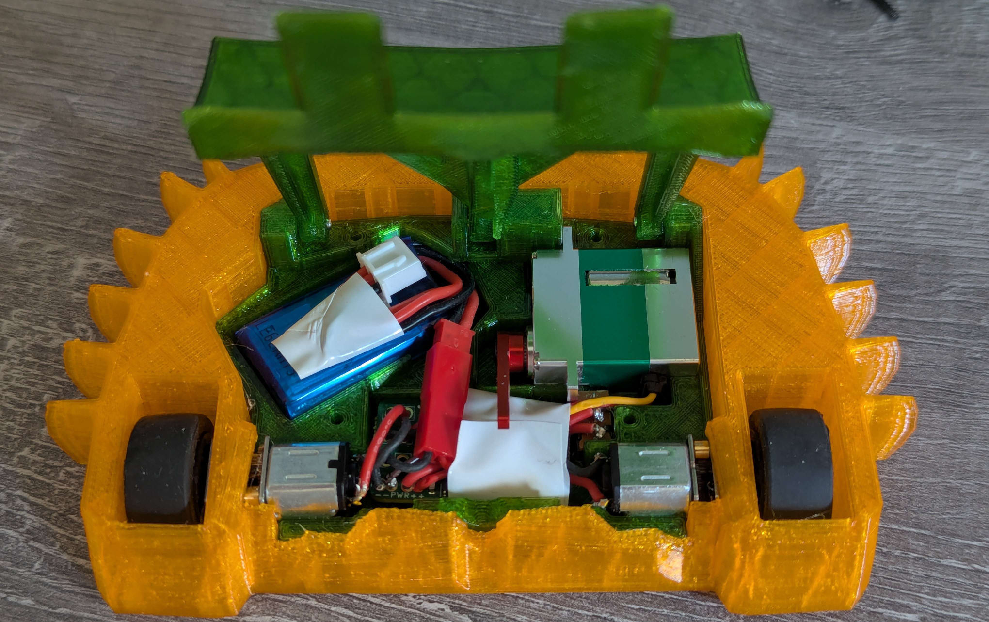
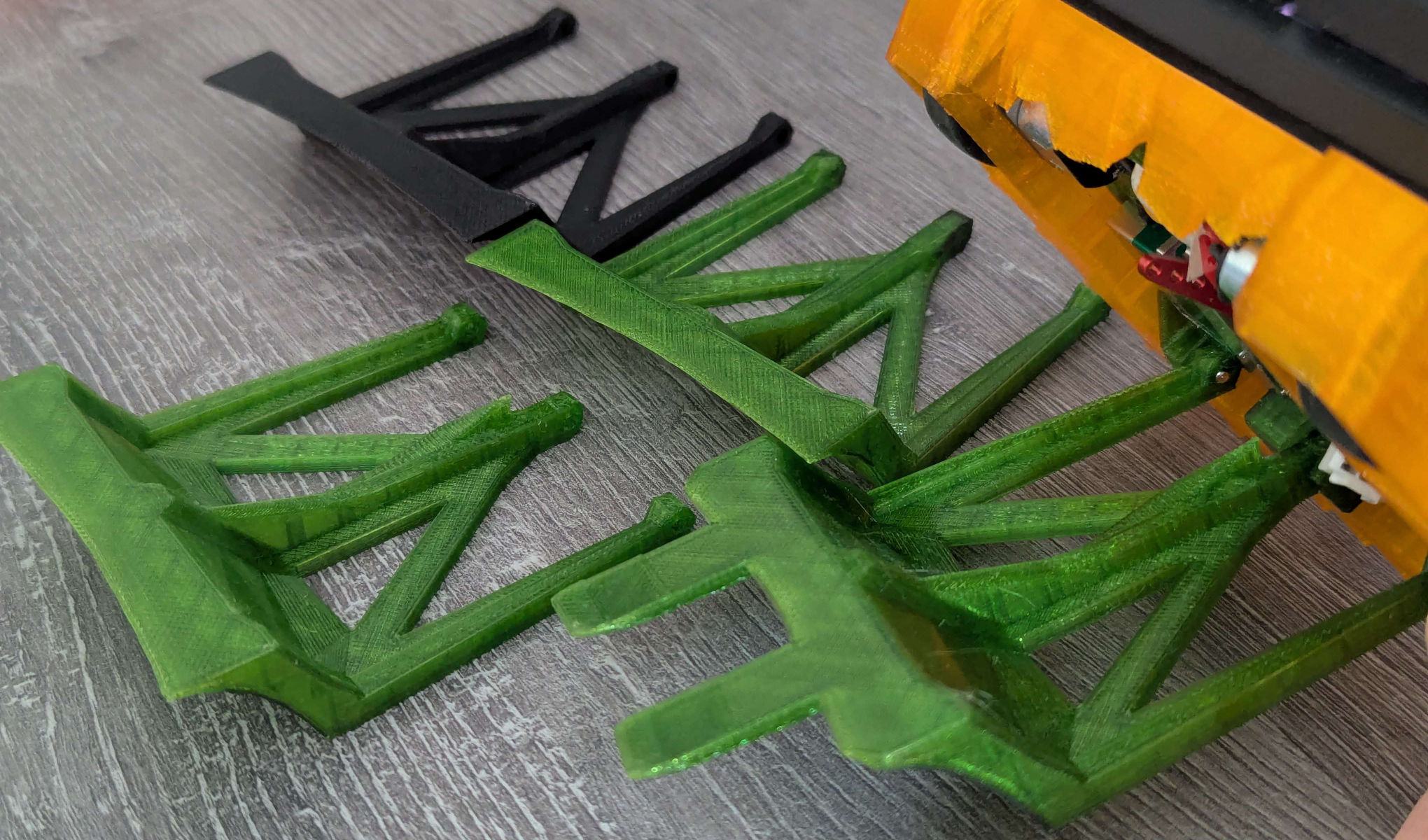
The flipper went through several design revisions, iterating on both the shape and linkage geometry. Initially the flipper had a flat underside that rode directly against the servo horn, but this gave too much torque throught the range of motion and not enough speed. Adding a curve to the underside changes the leverage through the stroke — high torque at the start for lifting, transitioning to higher speed as the flipper travels through its arc.
Originally the flipper lacked the front forks — these were added after testing showed it struggled to get purchase on test objects.
The flipper currently relies on gravity to return, which can create situations where the robot gets stuck. This is something I'd look to improve in future models. This could be done using a spring on the pivot pins, or maybe changing the design to constrain its movement to the servo horn so it gets pulled back down.
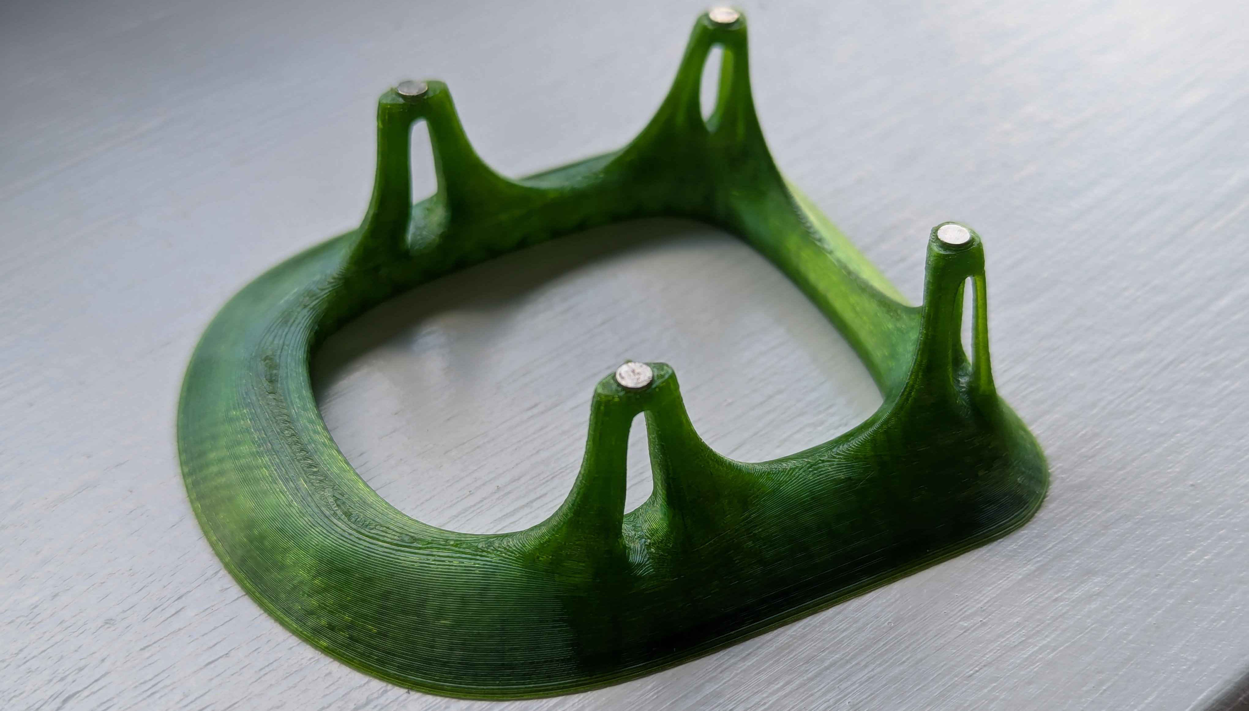
The regulations state that all robots must have a stand that seperates the wheels from the ground when not in use. As I used blender I decided to make something that looked a little fancy and took advantage of what blender can do.